Piping Isometric Drawings Examples
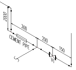
The isometric drawings are a group of documents tens or hundreds that are used to design pipe system in an industrial plant.
Piping isometric drawings examples. One run of pipe per isometric drawing branches of the pipe run or continuations are placed on other drawings typically shown as short portion of dashed line on main pipe run example of double line method showing existing piping iso drawings iso drawings connected piping usually a note indicates the name or specification of the branch line. On the previous example the mechanical flow diagram indicates a 6 line and a 4 pump nozzle. It is apparent that a reducer is necessary between the valve and the pump nozzle. This reducer must be shown on the isometric and called out as indicated in the example.
The larger pipe size is always given first. How to read a piping isometric. A pipe into a isometric view is always drawn by a single line. This single line is the centerline of the pipe and from that line the dimensions measured.
So not from the outside of a pipe or fitting. The image below shows a orthographic view of a butt welded pipe with three sizes a b c. There is a no size but stature most important p id there are drawings of size but not right ratio isometric with drawings only show ground floor piping ga have detailed drawings to each section pipe support. Isometric piping drawings are not scale drawings so they are dimensioned.
They are not realistic pipes are single lines and symbols are used to represent pipe fittings valves pipe gradients welds etc. Are tagged with the same codes used on the pid and ga. What is an isometric piping drawings.


